16x2 LCDs are most commonly used display units in microcontroller based projects. I got much information about LCD, LCD commands, LCD initialization etc from the below link and I hope, it will be very much helpful for beginners.

http://www.dinceraydin.com/lcd/intro.htm
Below is my final working code for 4 bit mode LCD with PIC16F877A: (HI-TECH C)


16x2 LCD WITH AVR (ATMEGA16 or ATMEGA32) - 4 bit mode
The above code is for AVR microcontroller. I am usign avr-gcc in linux.
Note:
Some bits of PORTC will be used for JTAG , which is JTAG enabled by default. So it may not work as normal IO pin if we didn't disable it in fuse bits. (HFUSE)
Now, the connections are not to be much explained since all is understood from the #defines in the above code.....
We can create a make file for the above purpose:
type make to build lcd.hex
type sudo make program to load it to avr
------------------------------------------------------------------------------------------------------------------------------------
16x2 LCD WITH MSP430 LAUNCHPAD (4BIT MODE)
MSP430G2231)

Since the launchpad works at 3.6v, we need to provide an external 5v supply to
power the LCD module. But we can directly connect the port bits of MSP430 to LCD..
Note:

Here is the final working lcd code for stellaris launchpad. Main source file is embedded below but it requires linker script, startup code and many headers so I am posting the link towards my git repo which have complete files required for all stellaris codes. If you have any doubt, u can ask by comments...
Here is a working code for stellaris launchpad.
https://github.com/vinodstanur/stellaris-launchpad
http://www.dinceraydin.com/lcd/intro.htm
Below is my final working code for 4 bit mode LCD with PIC16F877A: (HI-TECH C)
#include<pic.h>
#define _XTAL_FREQ 20e6
__CONFIG(0x3F3A);
#define RS RB2
#define EN RB1
#define databits PORTD
/*----------------PIC INITIALIZATION------------*/
void pic_init()
{
    TRISB2 = 0;
    TRISB1 = 0;
    TRISD = 0;
}

/*-------------LCD FUNCTIONS BEGIN--------------*/
void LCD_STROBE(void)
{
    EN = 1;
    __delay_us(1);
    EN = 0;
}

void data(unsigned char c)
{
    RS = 1;
    __delay_us(50);
    databits = (c >> 4);
    LCD_STROBE();
    databits = (c);
    LCD_STROBE();
}

void cmd(unsigned char c)
{
    RS = 0;
    __delay_us(50);
    databits = (c >> 4);
    LCD_STROBE();
    databits = (c);
    LCD_STROBE();
}

void clear(void)
{
    cmd(0x01);
    __delay_ms(2);
}

void lcd_init()
{
    __delay_ms(15);
    cmd(0x38);
    __delay_ms(1);
    cmd(0x38);
    __delay_us(100);
    cmd(0x38);
    cmd(0x28);            // Function set (4-bit interface, 2 lines, 5*7Pixels)
    cmd(0x28);            // Function set (4-bit interface, 2 lines, 5*7Pixels)
    cmd(0x0c);            // Make cursorinvisible
    clear();            // Clear screen
    cmd(0x6);            // Set entry Mode(auto increment of cursor)
}

void string(const char *q)
{
    while (*q) {
        data(*q++);
    }
}

/*-------------LCD END--------------------*/

main()
{
    __delay_ms(50);
    pic_init();
    lcd_init();
    TRISC = 0;
    while (1) {
        cmd(0x80);
        string("HELLO WORLD");
        cmd(0xc0);
        string("IT IS WORKING:-)");

    }
}
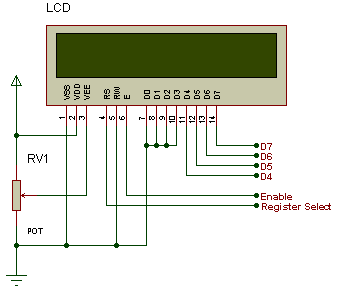
Connections:
-------------------------------------
LCD | PIC |
-------------------------------------
Register Select -->RB2 |
Enable -->RB1 |
-------------------------------------
D4 -->RD0 |
D5 -->RD1 |
D6 -->RD2 |
D7 -->RD3 |
-------------------------------------
CLOCK: 20MHz crystal oscillator
Also, any other frequency <20MHz could be used. But we need to edit the below line:
#define _XTAL_FREQ 20e6
POT --> 4.7k
16x2 LCD WITH AVR (ATMEGA16 or ATMEGA32) - 4 bit mode
#include<avr/io.h>
#define F_CPU 12e6
#include <util/delay.h>

#define RS 6 //PD6
#define EN 7 //PD7
#define databits PORTC //lower nibble
#define LINE1 cmd(0x80)
#define LINE2 cmd(0xc0)

void port_init()
{
    DDRC = 0xff;
    DDRD = (1 << RS)|(1 << EN);
}

void LCD_STROBE(void)
{
    PORTD |= (1 << EN);
    _delay_us(1);
    PORTD &= ~(1 << EN);
}

void data(unsigned char c)
{
    PORTD |= (1 << RS);
    _delay_us(50);
    databits = (c >> 4);
    LCD_STROBE();
    databits = (c);
    LCD_STROBE();
}

void cmd(unsigned char c)
{
    PORTD &= ~(1 << RS);
    _delay_us(50);
    databits = (c >> 4);
    LCD_STROBE();
    databits = (c);
    LCD_STROBE();
}

void clear(void)
{
    cmd(0x01);
    _delay_ms(5);
}

void lcd_init()
{
    _delay_ms(15);
    cmd(0x30);
    _delay_ms(1);
    cmd(0x30);
    _delay_us(100);
    cmd(0x30);
    cmd(0x28);            // Function set (4-bit interface, 2 lines, 5*7Pixels)
    cmd(0x28);            // Function set (4-bit interface, 2 lines, 5*7Pixels)
    cmd(0x0c);            // Make cursorinvisible
    clear();            // Clear screen
    cmd(0x6);            // Set entry Mode(auto increment of cursor)
}

void string(char *p)
{
    while(*p) data(*p++);
}

int main()
{
    _delay_ms(50);
    port_init();
    lcd_init();
    LINE1;
    string("HELLO WORLD");
    LINE2;
    string("IT IS WORKING:-)");
    while(1);
    return 0;
}
The above code is for AVR microcontroller. I am usign avr-gcc in linux.
Note:
Some bits of PORTC will be used for JTAG , which is JTAG enabled by default. So it may not work as normal IO pin if we didn't disable it in fuse bits. (HFUSE)
Now, the connections are not to be much explained since all is understood from the #defines in the above code.....
To compile it using avr-gcc(linux) and to burn it using usbasp, the command line are as follows:
avr-gcc -mmcu=atmega16 -Os lcd.c
now we get a.out (elf)
to convert it to hex,
avr-objcopy -j .text -j .data -O ihex a.out a.hex
Now we get a.hex file.
To burn it to atmega16 using usbasp (ISP programmer),
sudo avrdude -p m16 -c usbasp -e -U flash:w:a.hex:i
(for more details, read man page of avrdude, ie "man avrdude")
We can create a make file for the above purpose:
Makefile:
# AVR-GCC Makefile
PROJECT=lcd
SOURCES=lcd.c
CC=avr-gcc
OBJCOPY=avr-objcopy
MMCU=atmega16
PROJECT=lcd
SOURCES=lcd.c
CC=avr-gcc
OBJCOPY=avr-objcopy
MMCU=atmega16
CFLAGS=-mmcu=$(MMCU)
$(PROJECT).hex: $(PROJECT).out
$(OBJCOPY) -j .text -j .data -O ihex $(PROJECT).out $(PROJECT).hex
$(PROJECT).out: $(SOURCES)
$(CC) $(CFLAGS) -Os -I./ -o $(PROJECT).out $(SOURCES)
program: $(PROJECT).hex
avrdude -p m16 -c usbasp -U flash:w:$(PROJECT).hex:i
clean:
rm -f $(PROJECT).out
rm -f $(PROJECT).hex
type make to build lcd.hex
type sudo make program to load it to avr
------------------------------------------------------------------------------------------------------------------------------------
16x2 LCD WITH MSP430 LAUNCHPAD (4BIT MODE)
MSP430G2231)
Since the launchpad works at 3.6v, we need to provide an external 5v supply to
power the LCD module. But we can directly connect the port bits of MSP430 to LCD..
Note:
- Never forget to provide a connection between both the grounds of launchpad and external supply.
- Never connect the Vcc of MSP430 to any where on the LCD
- Ground the R/W pin of LCD
- Pull down the VEE of LCD with a 1K resistor or use a POT ..
- Use a 470 ohm resistor to provide the supply for the backlight LED..
/*
*MSP430 launchpad based 4bit lcd code..
*Assuming the clock is 1MHz..
*All delays are designed according to that...
*for eg: __delay_cycles(1000) => 1ms delay at 1MHz clock
*Otherwise use any delay routines, if available.
*Note:
In my previous codes, the initialization is not so perfect
because I deviated from the original specifications...
But those codes are at least working for me,, Any way,
now I am providing a better code which includes a
pseudo_8bit_cmd function since the LCD expects an 8 bit
command at first, before entering to 4 bit mode...

-Connections:
RS -> P1.0
EN -> P1.1
D7 to D4  -> P1.7 to P1.4
R/W to GROUND

-Compiler used: msp430-gcc
-Command line: msp430-gcc -mmcu=msp430g2231 lcd.c -mdisable-watchdog
-Burning code: sudo mspdebug rf2500
> prog a.out
> run

*/

#include<msp430g2231.h>

#define RS(X)     P1OUT = ((P1OUT & ~(BIT0)) | (X))
#define EN(X)   P1OUT = ((P1OUT & ~(BIT1)) | (X<<1))
#define LCD_STROBE do{EN(1);EN(0);}while(0)
#define databits P1OUT  // P1.7 - D7, ....., P1.4 - D4
#define LINE1 cmd(0x80)
#define LINE2 cmd(0xc0)

void port_init()
{
    P1OUT = 0 ;
    P1DIR = 0xff;
}

void data(unsigned char c)
{
    RS(1);
    __delay_cycles(40);  //40 us delay
    databits = (databits & 0x0f) | (c & 0xf0);
    LCD_STROBE;
    databits = (databits & 0x0f) | (c << 4) ;
    LCD_STROBE;
}

void cmd(unsigned char c)
{
    RS(0);
    __delay_cycles(40); //40 us delay
    databits = (databits & 0x0f) | (c & 0xf0);
    LCD_STROBE;
    databits = (databits & 0x0f) | (c << 4) ;
    LCD_STROBE;
}

void pseudo_8bit_cmd(unsigned char c)
{
    RS(0);
    __delay_cycles(15000); //15 ms delay
    databits = (c & 0xf0);
    LCD_STROBE;
}
void clear(void)
{
    cmd(0x01);
    __delay_cycles(3000); //3 ms delay
}

void lcd_init()
{
    pseudo_8bit_cmd(0x30); //this command is like 8 bit mode command
    pseudo_8bit_cmd(0x30); //lcd expect 8bit mode commands at first
    pseudo_8bit_cmd(0x30); //for more details, check any 16x2 lcd spec
    pseudo_8bit_cmd(0x20);
    cmd(0x28);             //4 bit mode command started, set two line
    cmd(0x0c);             // Make cursorinvisible
    clear();               // Clear screen
    cmd(0x6);              // Set entry Mode(auto increment of cursor)
}

void string(char *p)
{
    while(*p) data(*p++);
}

int main()
{
    port_init();
    lcd_init();
    LINE1;
    string("WELCOME TO");
    LINE2;
    string("MSP430 LAUNCHPAD");
    while(1);
}
HEX
:10F8000031408002B240805A20013F4000000F93F7
:10F8100005242F839F4F82FA0002FB233F40000004
:10F820000F9304241F83CF430002FC23044124537D
:10F83000B240805A2001B0126AF8B012F2F97F404B
:10F8400080FFB01204F93F4064FAB01238FA7F40EA
:10F85000C0FFB01204F93F406FFAB01238FAFF3F10
:10F8600032D0F000FD3F304080FA041204412453AE
:10F87000C2432100F24322003441304104120441CA
:10F8800024532183C44FFCFF5F4221005FD3C24F4A
:10F890002100034303433F400C001F83FE235F42CC
:10F8A00021004E4F7EF00F005F44FCFF7FF0F0FF21
:10F8B0004FDEC24F21005F4221006FD3C24F2100B3
:10F8C0005F4221007FF0FDFFC24F21005F42210017
:10F8D0004E4F7EF00F005F44FCFF0F5F0F5F0F5F26
:10F8E0000F5F4FDEC24F21005F4221006FD3C24F36
:10F8F00021005F4221007FF0FDFFC24F2100215314
:10F90000344130410412044124532183C44FFCFF8D
:10F910005F4221007FF0FEFFC24F210003430343FB
:10F920003F400C001F83FE235F4221004E4F7EF0BC
:10F930000F005F44FCFF7FF0F0FF4FDEC24F21005D
:10F940005F4221006FD3C24F21005F4221007FF050
:10F95000FDFFC24F21005F4221004E4F7EF00F009D
:10F960005F44FCFF0F5F0F5F0F5F0F5F4FDEC24F03
:10F9700021005F4221006FD3C24F21005F4221006E
:10F980007FF0FDFFC24F210021533441304104126A
:10F99000044124532183C44FFCFF5F4221007FF0C8
:10F9A000FEFFC24F210003433F4087131F83FE2306
:10F9B0005F44FCFF7FF0F0FFC24F21005F42210057
:10F9C0006FD3C24F21005F4221007FF0FDFFC24F85
:10F9D00021002153344130410412044124535F4338
:10F9E000B01204F903433F40E7031F83FE23344171
:10F9F00030410412044124537F403000B0128EF98C
:10FA00007F403000B0128EF97F403000B0128EF986
:10FA10007F402000B0128EF97F402800B01204F918
:10FA20007F400C00B01204F9B012D8F97F400600F4
:10FA3000B01204F9344130410412044124532183AB
:10FA4000844FFCFF073C1F44FCFF6F4F9453FCFFA7
:10FA5000B0127CF81F44FCFF6F4F4F93F4232153E7
:10FA60003441304157454C434F4D4520544F004D94
:10FA70005350343330204C41554E4348504144009C
:02FA8000001371
:040000030000F80001
:00000001FF
16x2 LCD with STELLARIS LAUNCHPAD:
Here is the final working lcd code for stellaris launchpad. Main source file is embedded below but it requires linker script, startup code and many headers so I am posting the link towards my git repo which have complete files required for all stellaris codes. If you have any doubt, u can ask by comments...
Here is a working code for stellaris launchpad.
https://github.com/vinodstanur/stellaris-launchpad
could you please the the wire connrctions between LCD and msp??
ReplyDeleteIt is written in the code
ReplyDelete-Connections:
RS -> P1.0
EN -> P1.1
D7 to D4 -> P1.7 to P1.4
R/W to GROUND
NOw see the first circuit diagram of LCD alone and connect accordingly...
thank you very for replying...valare nanniunde..I have connected according to the circuit only...but still it has not worked successfully.
ReplyDeleteI am using MSP430g2231 and the Code Composer Studio v4. Should i make any special step while executing the code??
I have done like this: First connected the circuit according to the circuit diagram,then connected the device to SYSTEM.Opened CCS,new proj,source.c,included mp430g2231 files,written prog,debugged n have given run...but instead of LCD, leds present in MSP device glown.
Could ypu please reply ofr the above mentioned issue??
ReplyDeleteOne more problem is some current from System is going to LCD.How to solve this issue???
I tried my code in linux (msp43-gcc),
ReplyDeleteIn your case if it is compiling correctly and not working while running the code, then I think the problem is the Watchdog timer resetting the mcu.
So,
add this line inside main, just as a first line in main function.
WDTCTL = WDTPW + WDTHOLD; /* Stop watchdog timer */
Now compile it and inform me if it is having the same problem.
In my code, I am doing this step in the command line itself but in your case you are using GUI, so it may not be including the disable watchdog feature....
what do you mean by "some current from system is going to LCD"?
ReplyDeletethank you very much for responding... i will try the solution and inform you..tnx
ReplyDeletei have added that command after
ReplyDeleteint main
{
......in the 96th line,still it is not working.
Should i take that txd,rxd jumpers out??
I took out jumpers at p1.0& p1.6.
I will give u a hex code.
ReplyDeleteTry it...
And report if it is also not working...
So we can decide if it is a hardware problem or software problem.
(I will update a hex code just below the source code)
What should i do with hex code?Should i paste the hex code in CCS and run??
ReplyDeletepls help me with the hex code.. we have tried our lcd JHD162 with 89s51 n it displayed.
ReplyDeleteCould you please reply for the above issue?
ReplyDeleteHi
ReplyDeleteCould it be posibel to cange pic to p16f690 insted of 877
Hope for you help
O.Damsgaard - DK ole@damsgaard-jensen.dk
Thank You!!
ReplyDeleteThank you for code :)
ReplyDeleteI have a problem.. Im using pic18f2550 and Mplabx C.. I tried everything for 4 bit LCD..still I couldnt run it..what should I do?
hi, i ran it in the version v8.60.
ReplyDeletebut LCD gives no output. But why help me..!!
Could it be posible to change pic to p16f690 insted of 877
ReplyDeleteHope for you help.
mizanur56@gmail.com
wat are the source files i hsv to add in mplab otherwise it is saying that no file arguments...
ReplyDeletehelp me..
Hi, I want to implement it in PIC16F690
ReplyDeletewith following conditions, is it possible.??
Register Select -->RA2 |
Enable -->RA1 |
-------------------------------------
D4 -->RB4 |
D5 -->RB5 |
D6 -->RB6 |
D7 -->RB7 |
What change do I need..??
Nothing is impossible. We are using only GPIO Pins. So just need to configure it accordingly....
ReplyDeletehi all,
ReplyDeleteI m using PIC 16F877a with Hi-tech compiler. I have done with serial communication and 4-bit LCD display program individually.
Now i want to merge these 2 to display serially received data.Till now i can receive correct data serially but LCD displaying wrong characters.
so tell me how i find the exact problem and how to solve it.
hi all...
ReplyDeletei am getting a linker problem while running the program in CCS compiler...
can any help me..
i am using stellaris launchpad lm4fh5qr...
Hi All,
ReplyDeletecan anyone provide me the code for lcd display 4 bit mode in pic 16f72. pls send me the code.
please send me program code for 4 bit lcd in picc in ccs compiler
ReplyDeleteif you having 4Bit lcd code in ccs compiler send me jaisurya446@gmail.com
DeleteHi, it such a great info for beginner like me, but what does 4 bit interfacing means??
ReplyDeletehii vinod... i want a 16x2 lcd display program for stm32f030 value line.....
ReplyDeletecan you??? :)
Thanks very much :)
ReplyDeleteAll in One - LCD interfacing with all MCU's.
ReplyDeleteAll in One place - really nice.
These links may be helpful
Interfacing 16x2 LCD with Stellaris launch pad
http://www.npeducations.com/2014/01/interfacing-graphical-lcd-jhd-128x64e.html
Interfacing 16x2 LCD with MSP430 Launch pad
www.npeducations.com/2013/10/interfacing-16x2-character-lcd-display.html
Sir, i use pic16f886 in this controller how to set the configure bits....
ReplyDeleteCan anyone help .. How do I display result obtained via ADC10 in MSP430 on LCD display
ReplyDeleteplease post above code for lm3s608 stellaris guru ic
ReplyDeleteSir, I copied ur code and build it succesfully...bt its not working on proteus. i made same connections as described by u.so plz help
ReplyDeleteyour code is working but i need an explanation on this
ReplyDeletevoid cmd(unsigned char c)
{
RS = 0;
__delay_ms(50);
databits = (c >> 4);
LCD_STROBE();
databits = (c);
LCD_STROBE();
}
if i say i want to send the clear command in binary 00000001
in your code first for high nible you shift right 4 places so we get 00000000
and then you send 00000001 again. i was expecting to see 00010000 for lower nible so as to have high nible 0000
low nible 0001
hi
ReplyDeleteI am using atmega16 interfaced with 16x2 LCD.I used your code and simulated using Proteus but it is not working plz help me its very urgent
Thanks in advance
This comment has been removed by the author.
ReplyDeletePlease provide a circuit diagram for the PIC16f877 project because mine ain't working.
ReplyDeletehi sir i was using pic16f1503 iam facing a problem while am interfacing it with 16x2 lcd in 4 bit mode..i was run it in proteus successfully ...but not in the hardware what are the problem may arise when we are do this thing in hardware i made the connection clearly and i put 40ms delay between reset and enable..please help me it s drives me crazzy
ReplyDeleteanne have you done it by 4 bit or 8bit
ReplyDeletepl change your website font it is very hard to read
ReplyDeletewhile i am trying to build it showing this are all __ undefined symbol.
ReplyDeleteAnyone has sample code for 16x2 LCD interface on launchpad with MSP430F5529? If so please provide me a copy..
ReplyDeleteThanks
Beeresh
Thank you for code :)
ReplyDeleteI have a problem.. Im using pic16f877A and CCS compiler .. I tried everything for 4 bit LCD..still I couldnt run it..what should I do? if anyone having send code for jaisurya446@gmail.com
Hi ,how to display string WELCOME on 16 x 2 display using energia and TM4c123gxl what is schematic for the same. actually ardiuno code can run on tm 4c123 gxl but lcd code of ardino is not working on tm4c123gxl...please help
ReplyDeleteit was a wonderful chance to visit this kind of site and I am happy to know. thank you so much for giving us a chance to have this opportunity.. best-24-inch-tvs
ReplyDeletePlasma flat screens offer HDTV goals, and screen sizes from around 37 inches and up. Costs extend from under $500 to a huge number of dollars for the bigger, top of the line models. Everything relies upon brand, size and highlights.Best 19 inch tvs
ReplyDelete