16 x 2 LCD controlled via power line

This 16x2 LCD is too traditional and still very much popular in the world of electronics and embedded system. I remember I started programming on PIC for displaying text on these LCDs around 8 years ago. Now I just found one of these LCD from my junk box and want to try it out because it is nostalgic. It reminded me the 4 bit data lines plus additional 2 control pins, a total of 6 minimum signal pins and obviously additional 2 mandatory power wires +5v and GND, so a total of 8 wires. If this display is designed in 2019, for sure it will have only Vcc, GND and a single wire data pin or in worst case the 2 wire i2c or TWI.

   Then I just thought why even 1 wire for data? Because we can easily multiplex the 1 wire data line with the Vcc line by keeping a diode + capacitor combination towards the LCD power supply pin.
I am using an arduino board to do the serial to parallel conversion + some packet parsing and lcd backlight brightness control. I am not a huge fan of Arduino but for this simple proof of concept, I don't want to bring out a Makefile folder with muliple files. I picked the Arduino UART RX as the serial receiver. RX pin is connected directly to the input Vcc, but before the schottky diode. After the diode a capacitor is used to hold the DC voltage when the Vcc gets modulated with the UART TX of the other end. Better explained in the below pic.


     (video demo of python script initializing the lcd and there after streaming data on second line)

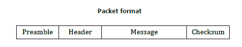
I haven't written any LCD related initialization in the arduino, I just used it for serial to parallel converter + backlight LED contrast control. So the entire display initialization could be sent from current-buffered UART port. There are 4 types of single byte commands which is implemented inside the arduino.

(x is lower nibble, command is higher nibble)
0xA[x] where x is the lower nibble which will be placed on LCD pins 4 to 7
0xB[x] where if x is 1, RS will be SET HIGH, if zero, RS will be cleared or SET LOW.
0xC[x] where if x is 1, EN will be SET HIGH, if zero, EN will be cleared or SET LOW.
0xD[x] where if x is PWM value for LED backlight, its range is from 0 to 15 where it gives max brightness at 15.

I am using a USB to UART converter to connect the device to my laptop. A python script is doing the lcd initialization and data streaming. A small modulator circuit is used to convert the UART TX low power signal to a power signal which can load high current. I cannot use the TX pin as it is because it cannot load the current which is required to operate the LCD with backlight. So this buffer circuit is used and I am using 9600 baudrate so that the 2.2K resistor is low enough to maintain the fall time when the output stage MOSFET  is OFF.  


         (Left mosfet: AO3400A n-channel,  right mosfet AO3401A p-channel)
Both mosfets are power mosfets with a bit higher current rating (say 5A) and for this application 200mA mosfets can also do the job,  but I don't have such low current rated mosfets, so I just used what ever available with me. We can do with NPN, PNP BJT aswell, but in that case, series base resistors needs to be connected to prevent base burnout).


The circuit and it's working is self-explanatory.  Default level of UART TX is high. So the left mosfet will be ON by default which turns ON the right side P-channel mosfet. This provides 5V power to the output, when uart TX  sends any bytes, it starts lowering the TX pin and that will cut the 5V power and the 2.2K output resistor will pull the power rail to zero. This zero is reflected to the arduino RX pin, but since there is a diode and a capacitor, the capacitor holds enough power to maintain the display circuitry to work when the power input is modulated to zero by the UART. The role of diode is to prevent reverse discharge of the capacitor and there by allowing the diode front-end voltage to follow the UART TX by not corrupting it. A schotkky diode is preferred. Also a low dropout is more preferred because this old LCD is kind of more strict about 5V input, if not the display fades, and there are some workarounds by giving negative voltage to VEE pin etc. So anyways, the RX pin see the signal as pure incoming UART bytes and it decode the byte according to the above mentioned 4 type of packets. It accordingly set the data lines, EN pin and RS pin.
Now a simple python script from PC side can imitate the LCD command and data along with the EN and RS control, the same was how we do with a microcontroller. The good part of this setup is that it is just working with 2 wires which provides the power to the system, so may be we can say a kind of simple DC power line communication.


Photos:


    (arduino nano or micro (or what ever)  on bottom side of LCD with the diode + capacitor)

 (modulator or in other word, a powerful high current capable UART TX )         


Fimware and python script:

Qi wireless power receiver from scratch


Hello all,

Now a days Qi wireless power transmitters are becoming more and more popular for charging mobile phones and most of the mobile phone manufactures are now adding the Qi power receiving circuitry into their handsets. Also various wearable technology products like smart watches, fitness trackers etc are also now using wireless charging. Qi is not the only standard, but Qi is kind of most popular now for low and medium power devices.

What exactly is this wireless charging or magnetic resonance based wireless power transfer ?
          A transformer basically is very simple static (or stationary) electro-magnetic passive electrical device that works on the principle of Faraday's law of induction. But imagine a transformer without proper core and the primary and secondary coils are not coupled properly by keeping those few millimeter apart. In this case the coupling factor reduces which reduces it's efficiency and received power. To overcome this to an extend, a series capacitor is added to the transmitter and receiver coil. Now we all knows there will be a resonance frequency for an LC circuit. When the transmitter drives the LC circuit with a frequency near to the resonance frequency, it's current increases and the Inductor voltage increases. Now similarly when a receiver is also tuned to similar frequency, it's tendency to pull the energy of it's natural frequency will be very high. This can be related to a radio receiver, the basics of any radio receiver will be a resonance LC tank circuit which will be either tuned manually or using a varicap diode. You can find some better explanation by googling about resonance coupling.

Now why Qi or any standard for wireless charging ?
       We can make a very cheap wireless power transmitter circuit using a 555 IC and push-pull mosfet circuitry along with an inductive coil and a series capacitor. Same way we can make a receiver as well by matching the resonance frequency and a schottky bridge rectifier. But these circuits, especially the transmitter circuit is not at all safe. If any metalic object is kept near to or on top of this transmitter, it will heat-up due to eddy current generation (similar to our induction cooker at home). The transmitter doesn't know if it is a power receiving coil or a foreign metallic object. So there is a need for a transmitter to identify the authenticated receiver and then only transmit true power over the air. So definitely there is a need for the transmitter to identify a proper receiver to transmit power. Qi is an open interface standard that defines wireless power transfer using inductive charging over distances of up to 4 cm (1.6 inches), and is developed by the Wireless Power Consortium. Also there should be a common standard for this so that different manufacturers can make transmitters and receivers independently which are compatible to each other.
    Another requirement is to increase or decrease the transmitter power on demand by the receiver. This can also be achieved by continuous feedback from the receiver to the transmitter.

How the receiver send data to transmitter via the same charging coil ?
      When the receiver circuit receives the ping energy from the transmitter (which is on for few milli seconds), the receiver control circuitry detects the ping and modulate the same receiver coil with a 2KHz bi-phase modulated signal according to the Qi protocol standard. This is achieved with a pair of MOSFETs pulling and releasing both ends of the RX coil via a relatively smaller capacitor (much less than the resonance capacitor). This pulling-releasing mechanism will reflect the 2KHz signal on the RX coil and that immediately reflects on the TX coil as well. This is similar to RFID/NFC back-scatter modulation.

The transmitter periodically sends short PING energy signals on air and if the receiver respond with proper ping response packet according to the Qi packet structure, it starts the receiver identification process followed by continuous power transmission. (Not exactly, I just simplified it. More specific details are there on the documents which is attached towards the end of the blog post).
      Now the receiver need to send back periodically how much power is received and the error correction packet which tells the transmitter to increase or decrease the energy transmitted. When the transmitter receives positive error packet, then the transmitter increases the transmission power by moving towards the resonance ie by climbing the hill from the right to left. 


Even though the name is resonance coupling, never get confused that it always works at resonance. Generally these devices try to keep a bit away from resonance or in other words keep higher frequency offset from the peak resonance frequency because they can self adjust to increase or decrease the transmitted power on demand for various (few mm) distances from the transmitter coil. Also if load require more current, it can demand the transmitter to increase its power. But still it wont move exactly to the resonance, it just stop before reaching the resonance point because things will get a bit out of control exactly at resonance especially in series LC resonance transmitter circuit due to very high current and higher resonance voltage on the coil.

Communication protocol:

Bit encoding scheme
The Power Receiver shall use a differential bi-phase encoding scheme to modulate data bits onto the
Power Signal. For this purpose, the Power Receiver shall align each data bit to a full period tCLK of an internal clock signal, such that the start of a data bit coincides with the rising edge of the clock signal. This internal clock signal shall have a frequency š¯‘“CLK = 2±4% kHz.
NOTE A ripple on the Power Receiver’s load yields a ripple on the Power Transmitter’s current. As a result, such a ripple can lead to bit errors in the Power Transmitter. The number of bit errors can be particularly high if this ripple has a frequency that is close to the modulation frequency š¯‘“CLK. The Receiver shall encode a ONE bit using two transitions in the Power Signal, such that the first transition coincides with the rising edge of the clock signal and the second transition coincides with the falling edge of the clock signal. The Receiver shall encode a ZERO bit using a single transition in the Power Signal, which coincides with the rising edge of the clock signal.


Byte encoding scheme
   The Power Receiver shall use an 11-bit asynchronous serial format to transmit a data byte. This format consists of a start bit, the 8 data bits of the byte, a parity bit, and a single stop bit. The start bit is a ZERO. The order of the data bits is LSB first. The parity bit is odd. This means that the Power Receiver shall set the parity bit to ONE if the data byte contains an even number of ONE bits. Otherwise, the Power Receiver shall set the parity bit to ZERO. The stop bit is a ONE. Figure below shows the data byte format including the differential bi-phase encoding of each individual bit using the value 0x35 as an example.


Packet structure
The Power Receiver shall communicate to the Power Transmitter using Packets. As shown in below figure.

Packet consists of 4 parts, namely a preamble, a header, a message, and a checksum. The preamble
consists of a minimum of 11 and a maximum of 25 bits, all set to ONE according to the above mentioned bit encoding scheme. The preamble enables the Power Transmitter to synchronize with the incoming data and accurately detect the start bit of the header. The header, message, and checksum consist of a sequence of three or more bytes encoded as above mentioned byte encoding scheme.


My receiver:


I have only two aims while trying this. The receiver should get powered by the transmitter continuously.  I should be able to control the power received by adjusting the error packets, in my case I am trying to keep received voltage always 10v.

There are lot more but I am only interested in this two features for now, so I will not be following the complete Qi specs described on the WPC documents, by the way, it worked for me without any issue.
This is purely experimental.


     (Will redraw the schematic in few days)


Ultrasonic audio transmitter and receiver system

Hi all, this is another mad project.  Aim of the project is to transmit laptop audio via ultrasound to few meters and then receive it and demodulate it and playback the audio on a speaker. 

       Checkout the below video

    The interesting part over here is that a low frequency sound wave (Say 1 to 4KHz) is modulated on another high frequency (40KHz) sound wave and the end result cannot be heard by a human and it is still a longitudinal wave. Now this amplitude modulated ultrasonic signal can be transmitted to a few meters and can be received by an ultrasonic receiver device and can be demodulated using a simple diode based envelope detector, the same way we do on an AM receiver.
 I thoroughly enjoyed the build, even though I know this is not going to be a useful project as it is, that is why at the top I mentioned "mad project".
      Generally these 40KHz transducers are mostly commonly used in distance meter modules and the typical application is that only. I took these transducers from a distance-meter module. So I thought of trying something different from the common application, and that is the reason I did this. Just a weekend time pass. :)

User space LCD driver for Raspberry pi zero


 I tried to get a raspberry pi zero a couple of months ago but I couldn't get one because of its demand and availability in India. But my friend Michael Kohn from Missouri sent me a pi-zero camera version. Thanks Mike :)

Dual boot for arduino

Hi all,

      I would like to introduce a new dualboot feature which can be an add-on to any existing arduino boards. The additional requirement is an external i2c eeprom with minimum size of the internal flash memory.


Here I modified the arduino bootloader and added additional functionality to backup and swap/restore between main flash memory and external backup eeprom which is now like a dualboot system. When the reset button in arudino is pressed, it enters to the bootloader mode. In my case, in bootloader it checks if the pins 10 and 11 are shorted while reset is invoked. If yes, the on board LED will glow for 1 second. If I remove the short between pin10 and 11 before the LED turns OFF (1 second TURNOFF timeout) it enters to dualboot mode and start swapping the main flash memory with external eeprom memory till "32KB - bootloader size". Now the existing flash binary is saved in external eeprom and previous binary is booted to the memory and it started executing. If we do the same operation again then it repeats the memory swap process and then previous application is again loaded or reverted back by creating a new backup of the existing application binary. So now we can maintain two codes in hardware and can be selected at any time.

If we are not doing the pin shorting (11 and 10) while hardware reset, it works like a normal arduino bootloader ie we can use an arduino IDE and load any sketch to it. (here I am selecting UNO even my board is mini pro 16). So it is again arduino compatible, obviously it should be right?!


Source code:
https://github.com/vinodstanur/arduino_dualboot_bootlaoder


stm32f407 discovery board as a 100MHz FM transmitter using crystal feedback trick

Hi All,
     It's been a long time I haven't updated my blog coz it is hard to get some free time.  Anyways, I have a small hack to share now.

This is a very simple hack, the aim of this project is to transmit a song stored in STM32F407 flash memory over air by FM at 100MHz. At first you can have a look at the below video, a weird demo taken through my mobile phone. A fixed song is repeatedly transmitted from the stm32f407 discovery and it received on a mobile phone FM radio which is tuned at 100MHz.


How it works?

 A song + voice in wav format is saved in the flash memory from an offset after application code.
The *.wav can be directly dumped into the flash say from address 0x08005000 after renaming the file as *.bin.  This can be done directly by using ST-LINK utility in windows.

Now a small application code is written which starts at 0x08000000 which will read the song file at location 0x08005000 and throws the bytes to a PWM pin. This is done repeatedly in an infinite loop by a timer interrupt which is configured according to the sampling rate of song+voice wav. It can be done by DMA as well.

Now one more thing, the system clock is derived from 8MHz external crystal oscillator. Using the internal PLL, the system clock is set to 100MHz. Now the Master Clock Output option is enabled to toggle a pin (PA8) at 100MHz. So the carrier frequency for FM is ready!

Now if we run the code, the PWM pin (PE9) will get the song data in a pulse width modulated format. An RC filter is connected to this pin to demodulate it and thus we will get a decent analog song signal. If we connect a earphone or an amplifier over here, we should be able to hear the song.

 Fine, now how to transmit the song over air?

"Crystal feedback hack"

The trick over here is to disturb the crystal oscillator according to the song data. For this a 22K resistor is connected from the analog song signal to one of the crystal PIN. This setup will load the crystal circuitry according to the instantaneous amplitude of song signal. The frequency of the crystal is getting affected by this. In simple words, frequency modulation is happening over here. The song data is getting modulated over 8MHz.

We already set the MCO pin to toggle at 100MHz. Since the 100MHz is generated from the 8MHz crystal clock, the modulation will be observed in the 100MHz signal also (obviously magnified). The feedback resistor 22K is selected in such a way that it won't affect the working of the crystal circuitry and won't do over modulation. We can play with these values later.


Done!

Sorry, need to connect an antenna on pin PA8 to transmit the signal properly over air.
For time being, I connected a small female jumper wire which was more than enough for the demo.


Yes, now it is done. :)

I am getting range of around 30 meters with this simple 20 cm wire antenna. If we connect a proper quarter wave length wire/telescopic antenna, the range may increase beyond 100meters as well.


(In below photo you can see a 22K resistor connected from RC filter output to crystal pin.
That is the only external hardware modification for FM modulation)


RC filter:
 R = 100 ohms
 C = 0.1 uF


Feedback resistor:
  R = 22K. (Remove R24 and short those contacts and connect feedback resistor from filter output to R24 pin as in the above photo)

The same experiment can be done by connecting an SD card and can transmit the song over the air the same way...... May be we can use helix mp3 decoder to play mp3 files from sd card and can do the same crystal feedback hack...


Thanks to ST for providing a nice GUI tool called stm32CubeMX which generates the initialization code for clock, MCO settings, timer settings etc. This makes the development process much easier and no need to dig into the datasheet to configure the registers.


Source Code:
https://github.com/vinodstanur/stm32f407-fm-transmitter 


Hex file with audio:
STM32F407_FLASH_HEX.hex


Disclaimer:
  Try it under your own risk.
 This project is for educational purposes only and is not intended to interfere with any radio channels in restricted/commercial bands. Neither site nor I, am liable for careless actions. Please check for the legality before attempting the project within your area. Since the GPIO toggling is not sinusoidal, higher harmonics will be there in the transmitted signal, so be careful while trying it out as it can transmit harmonics in restricted band.

Happy Christmas and Happy New Year from Attiny13


While trying to open a chinese camera pen, unfortunately the PCB inside it got damaged. Few of the PCB traces got cut and it became useless. After few days, I removed an 8 pin IC with SO8 package from the PCB. I was curious to know what it is, so I googled the part number 25FW406A but I couldn't find any exact match. I found some part number similar to that and I concluded that it is an SPI flash. Later I got a datasheet from 'ON semiconductor' for a similar part -LE25U40CMD which is a 4M-bit SPI flash memory. I soldered the IC on a common board, powered it with 3.3v and interfaced it to a TI stellaris launchpad via SPI port. According to the datasheet the SPI port need to be initialized in mode 0 or 3. I tried few commands listed in the datasheet and got proper response from the chip, the CHIP ID doesn't matches but that is expected because it is not the same part. I wrote functions for erasing, reading and writing the flash memory and tested it successfully using the launchpad.
       Then I thought of making an audio player using this chip which can play 8K mono wav file for around 1 minute. I selected Attiny13 microcontroller for this project. It is always fun to do some thing with limited resources. Attiny13 MCU is having 1KB flash and 64 bytes RAM. Also it is an 8 pin MCU. There are 5 GPIOs. I don't want to change the reset pin as a GPIO because I want to program it via ISP while developing the firmware.

STM32F429I-DISCO

Hi all,
    I am so much excited to play with STM32F429I-DISCO board which is having an arm cortex m4 microcontroller with external RAM of 64Mbit. Also the most exciting part of the board is 2.4" QVGA TFT LCD and a gyro. The microcontroller is having 2MB and 256KB internal FLASH and RAM respectively.
          I am planning to do many things on this board, like 3gp/mp4 video player (if possible,but not sure), oscilloscope with external high speed ADC, interactive video games, simple voice recognition, 3D rendering and many more.  Also you can expect an article on how to develop applications on this board using completely free and open source tools (arm-none-eabi-xxx) in linux environment.
          Ordered the board from element14 and eagerly waiting for it. Stay tuned, will be updating with exciting projects on  STM32F429I-DISCO.


Stellaris launchpad based video player


 (stellaris launchpad playing 320x140 color video at 25 fps video)


Hi,
 I am introducing my new mad project, a video player using stellaris launchpad and a 320x240 color lcd which I got from seeedstudio.  I tried the lcd shield by connecting on an arduino board and loaded some example codes for the arduino and it was working fine. I made a small video player few months ago using atmega32 and a 128x128 color lcd. This time my lcd resolution is larger. I want to make a better video player this time, so I selected a 32bit processor with more speed and ram, and I already have one arm cortex m4 based board, the texas instruments stellaris launchpad board which I bought for 4.9$ (limited time offer).
      I checked the arduino library code and written the lcd code for stellaris. To display stuff more faster I connected 8 bits of portb of stellaris to the 8 bit bus of lcd. At first I have some problems and later I found that few bits of portb is shorted with some other bits using zero ohm resistor r9 and r10, so I removed those. This is for msp430 launchpad compatibilit and it started to work.  I displayed some patterns on lcd and confirmed it is working.
  Later I configured uart in stellaris and streamed the image pixel data from pc to stellais and displayed it on the lcd. I used python image library in pc to convert image to 320x240 resolution and to get the pixel data from it.
    Later I configured sd card and used my own old library written for avr. Copied a single image data to sd card from sector zero and read the data and displayed on lcd. Then I wrote a python code in pc which invokes ffmpeg to obtain frames of a particular video. The same script reads all the image frames in the same order write the pixel data to a single file in 16bit format. Now I got a single uncompressed 'video' file!. I copied it to sd card, right now I am not following any filesystem, just writing the data from sector zero of sd card using  command 'sudo video_data >/dev/mmcblk0'.  (warning) The above command will overwrite the boot sector, root directory etc etc of existing file system in the card and there after the memory card will be shown as corrupted and will need to format it if you need to use it again in a PC/mobile phone. All data will be lost after this action.
        Now my aim is to display (stream) the data from the sd card on lcd. For this I am using multiple sector read command for the sd card and I am not even reading data to any buffer, instead I am directly reading from spi and writing to lcd. To get the best speed I optimized the HAL for SPI by sacrificing little bit on the readability of the code. Right now without audio I can achieve a speed of around 40 fps.
        Later I added audio to the video file, here I need to apply simple math. Using ffpmeg I extracted audio from the video in 8 bit wav format. On adding few video byte to video_file I added few audio bytes in between according to the video/audio bitrate ratio.

 Math:
    Video frame rate = 25
    single video frame size = 320x140*2
    So total video bytes/second = 320x140*2*25 = 2240000
    Now  I selected audio byte rate as 22400 bytes/second.
    So video/audio = 100
    So accordingly I have to mix video and audio in the final uncompressed video file.

 I configured pwm in stelaris. Then copied the new generated uncompressed video file to sd card in the same manner I did earlier. Now in the display code I need to send the video bytes to lcd and audio byte to pwm, and it played video with sound and the quality was decent....Checkout the above video..

Resistive touch screen based wireless mouse

Hi, after a long time I am updating my blog again. I bought few nokia color LCDs and resistive touchpad last month, all are chinese clones and very cheap. Then I thought of doing some thing with the touchpad at first. My previous blogpost  was a TV remote based computer mouse. So I decided to make a similar stuff using the touchpad and bluetooth...
         I have used a cheap ATtiny13 (8pins) microcontroller which runs at internal 9.6MHz clock. It samples two channel analog voltage from the touchpad. One of the GPIO pin is configured as a software uart TX (bit banging) which will stream the mouse data at a baudrate of 115200 (may need to calibrate by changing OCR0A little bit up or down) to a PC via bluetooth (HC_05 bluetooth module). Apart from the mouse cursor movement, I have implemented left click, right click and wheels on the same touch screen.
       A python script running on the pc will accept the mouse data and it will process the data and apply a smoothing filter to make the cursor movement more efficient. Right now I did the code for linux but will be easily portable by small modification in the python code.
        The only demerit is that we cannot do any multi-touch since it is a resistive touchpad.... Also it is not so easy to use with naked finger, instead a stylus is recommended for smooth operation. But any way in the video demo you can see its working fine with my finger........(I am using my fingernail ;-) ).....
       The bottom left part of the touchpad is configured as left click, bottom right as right click and 1 thickness from the right is for mouse wheel ...

TV remote controlled computer mouse (an avr VUSB project)


 Hi,
    While laying in bed and watching movies on my laptop, I used to think if there is a remote control, it will be easy to pause, play, fwd, rev, adjust volume, play next etc etc without going near to the system. Then I planned to make a remote control. I don't have a bluetooth mouse. There are many options infront of me. We can do it easily using AVR microcontroller because there is a great VUSB project :-). Using vusb library, we can implement a low speed software usb port(slave) on avr microcontroller. In the vusb library, there is an example of hid-mouse implementation in which the author used the usb report descriptor same as that observed on a logitech usb mouse. I then added few more lines of code to it to make it receive and decode RC5 signal from a philips tv remote and to send the corresponding mouse events to the system using vusb library. I believe this is the best method because it doesn't require any special driver in pc since it is a HID device. Also it works on almost all avr microcontroller(tiny, mega etc) and it doesn't require any usb to serial converter or any special hardware and it is cheaper. Also it is platform independent. It will work similar to that of a usb mouse in windows, linux & mac . I used obdev's shared VID/PID pair(0x16c0/0x5dc). The same pair is used in usbasp, so the usbasp driver should be uninstalled(if it is installed earlier) and deleted otherwise it will not work in windows.
       Hope all avr lovers have heard the famous USBASP AVR ISP programmer and most of them might have used/still using this VUSB based stuff. I then made the circuit design almost similar to that of the usbasp so that any one can try this easily on the same USBASP hardware just by replacing the atmega8 with another atmega8 programmed with the new hex from this project. Also we need to connect a TSOP 1738 IR receiver module to the USBasp hardware and need to connect it's o/p to the INT1 pin of Atmega8. Finished! Hardware is ready... Now we can plug it to usbport and use it is as an RC5-Mouse. We need a philips TV remote with RC5 protocol to test it.
       RC5 decoding is done using external interrupt and a timer. The mouse data consist of 4 bytes. The first byte is the mouse button states, the next two are dx and dy (increment in x and y coordinate, signed value) and the last byte is the wheel displacement which is also signed. We need to set the vaues of this four byte structure and then need to call a vusb function  "usbSetInterrupt" to send the mouse data to system. There is a very good vusb tutorial at codeandlife.com. Also you can check out the vusb home page.

Usage & Features:
  • 8 directional navigation of mouse pointer. (remote buttons - 2,4,6,8, 1,3,7,9)
  • Accelerated mouse movement for intelligent fast movement. ie the mouse pointer speed increases on holding the above mentioned navigation keys.
  • For fine adjusting the position, release the key and press it again step by step.
  • Left click - button 5
  • Right click - button 0
  • Mouse wheel - volume- and volume+ button

Playing video on nokia color LCD just using an 8 bit AVR! [A mad Project ;) ]

A MaD PROjECt....;-)


SD CARD + ATMEGA32 + NOKIA COLOR LCD = VIDEO PLAYER!!!
Hi,
I am introducing my new video player made using an atmega32 microcontroller and nokia color LCD. I got a 65K color LCD from an old nokia 6030 mobile phone.  I directly soldered 10 thin enamelled coper wire from the 0.5 cm square area of the thin flexible pcb of the LCD to a berg strip fixed on another board. For me it was the most difficult part of this project because I don't have any tiny tip soldering iron and an lcd connector (5x2) socket with me.
   After that I interfaced the lcd with atmega32 via SPI. Then initialized the lcd and displayed some color patterns and confirmed the LCD is working.
    Now my next step is to display a still image on the LCD. I used python image library to extract pixel information from any image file (jpeg, png etc) and I streamed it to avr via uart using pyserial and displayed the image successfully on the LCD with 16bit color depth. 
    After that I used an SD card to store the converted pixel information (132x132*2) bytes/picture. Then I interfaced the SD card with same SPI of atmega32 and displayed the image stored on it. I used FAT16 filesystem. The sd card part is not a problem for me because I have already done more projects on SD/MMC cards and I copied my previous code for that. 
    So after displaying the still image, I thought of making a slide show on the lcd. For that I wrote a python script to convert all images in a folder (on my pc) to a 132x132x2 byte files which is nothing but the uncompressed pixel information stored as new files. Then I copied all these converted files to SD card (file.lcd) and displayed them as an image slide show with 1 second time gap between each image.
    Since I successfully did the image slide show, then suddenly the idea of making a video player came to my mind. Because video is nothing but a slide show at high frame rate. 
   Then I used ffmpeg to convert a sample video to frames at 15 frames/second & 132x65 resolution. Then I used my python script to convert each still images to pixel information at 16 bit/pixel. Here instead of making small small files, I just collected all the picture information of adjacent frames into a single file and named  as my_video.lcd. Then I copied that file to memory card and modified the avr program to display it on the LCD. It access the FAT16 file system, then search for *.lcd files and if found, it returns the starting cluster address of that file and then stream that cluster to the LCD very fast. NOW VIDEO IS PLAYED (without audio)!!!!! ....Almost half of the project is finished....
Next half: (audio mixing)
       I played 15 fps 16bit/pixel on the lcd. Now comes the next headache. Video should have audio. :-(.... Then I started thinking how to include audio. I used ffmpeg(in pc) to extract audio from the video file to 8 bit mono wav. Since wav is uncompressed audio, it is easy to handle it using a microcontroller with hardware PWM. Then I modified my python script. I just opened the wav file and discarded the first 44 bytes (wav header) and then after that, I read the audio sample byte by byte and injected it in between the video information after some calculations(see the math below) related to the bit rate of both audio and video to decide the mixing ratio.
         For the perfect audio video synchronization, I implemented an error correction code in the converter, which monitors the synchronization error while mixing the audio-video bytes and when the error reaches a threshold value equivalent, it writes a dummy audio sample instead of real audio sample and thus prevents the accumulation of error and thus perfect audio video synchronization is achieved for hours of continuous video playback..
  Now in avr, i need to extract the audio and video and need to send the audio to an audio circular buffer which will be send to PWM using a timer interrupt and video directly to LCD. If any single byte mismatch occurred between the video and audio byte, every thing will get collapsed. I then modified the avr code to do as above and finally I played video with audio! :-) 

Getting started with ARM Cortex-M3 on GNU/Linux


STM32VLDiscovery is one of the three[2][3] cheap ARM Cortex-M3/M4 boards from ST. It contains an STM32F100RB microcontroller and an on-board ST-Link. Also it is designed to be powered with usb or external 3.3v or 5v. It seems to be a nice board for beginners. We can easily get started with stm32 on linux.

We need to build the toolchain for the bare metal arm ie the binary is to be executed on the arm without any linux/os. Summon-arm-toolchain is a shell script which will download the source of bintutils, gcc/gdb and two or three other packages (newlib, openocd and libopencm3) and compiles them (after applying some patches) to get executables for a "bare-metal" arm toolchain. After cloning the git repo, we need to read the README file, it says we need to install some essential packages before running the shell script. After that we just need to run the sheel "./summon-arm-toolchain" and it will do the remaining job. Finally we will get a new folder ~/sat in which we could see the library files and binary of arm-non-eabi-gcc and and many other required tools.
   Now we need a program to burn the binary to the hardware. For that we can use stlink. A simple make will generate the st-flash program...

two servo walking robot using TI launchpad


       Hi, I bought two small servo motors last month. I was thinking what I can do with this two servo, since it is only two in number. Then I asked this to my friend Achu Wilson and he suggested me to try a four legged two servo walker and he shown a youtube video in which some one demonstrating it. Then I also got interested to make some thing similar to that. Then I started designing my walker using two servo and msp430 launchpad and at last it turned out even better than I thought it would.(See the video above). The servo controlling techinque used here is a little bit different compared to the usual hardware PWM, I used a circular buffer to save each servo position and o/p pin details. Only a timer compare interrupt is used for this. This is a common technique used for controlling more servo using a cheap microcontroller with limited hardware Timer-pwm modules. Using this software pwm(not a perfect pwm, but still it will work in the servo motors) techinque, I can control more servo motors like 4,5, 6 etc etc depending on the number of I/O pins. 
     Coding for this msp430 launchpad is done in asm just because I also want to refresh the msp430 assembly language programming. I used naken430asm assembler in linux for the purpose.

Photos: